WeChat
CJEE
Journal of Electrical Engineering ›› 2018, Vol. 13 ›› Issue (3): 34-41.doi: 10.11985/2018.03.005
Previous Articles Next Articles
Cheng Li1,Tianqi Xu2,Yan Li2
Received:
Online:
Published:
Contact:
Abstract:
When the power grids with close voltage levels, the design of tie auto-transformer would become difficult due to the low effectiveness coefficient. This paper proposes a novel design of auto-transformer with common core for constant flux and variable flux. Through three-dimensional electromagnetic field simulation and calculation, the no-load main flux distribution, voltages of windings as well as important parameters such as winding short-circuit currents and short-circuit impedance of the transformer are analyzed calculated. The simulation results basically coincide with the results from estimating, which illustrates the feasibility of the new structure. By adopting this transformer with new structure, the primary material cost and no-load loss as well as transport weight can be effectively reduced. Furthermore, with simplified structure, the transformer can be manufactured with lower difficulty level, and the operation reliability would be enhanced consequently.
Key words: Constant flux, variable flux, auto-transformer
CLC Number:
TM411.3
Cheng Li,Tianqi Xu,Yan Li. A Novel Design of Auto-Transformer with Common Core for Constant Flux and Variable Flux[J]. Journal of Electrical Engineering, 2018, 13(3): 34-41.
0 / / Recommend
Add to citation manager EndNote|Reference Manager|ProCite|BibTeX|RefWorks
URL: http://www.cjeecmp.cn/EN/10.11985/2018.03.005
http://www.cjeecmp.cn/EN/Y2018/V13/I3/34
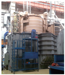
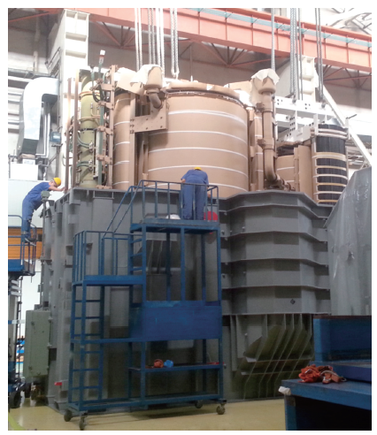
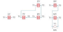
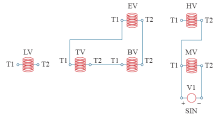
Fig.1
Lifting diagram of dual body transformer"
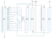
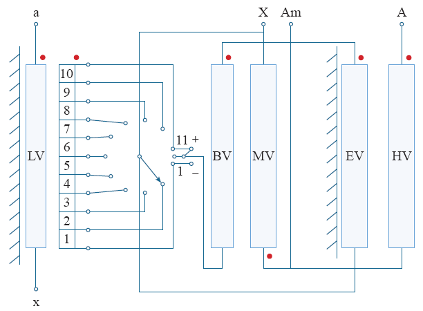
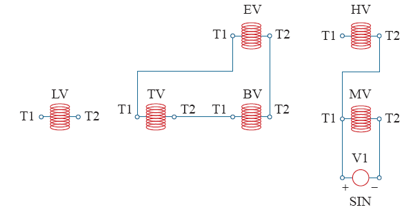
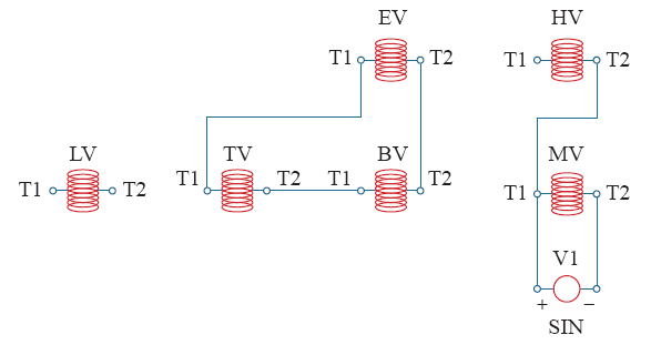
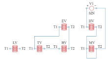
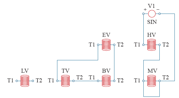
Fig.2
Wiring diagram"
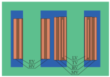
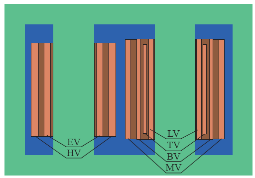
Fig.3
Diagram of winding arrangement"
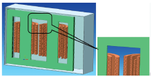
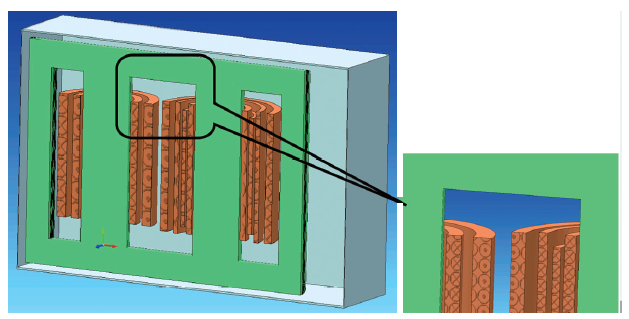
Fig.4
3D modeling"
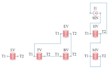
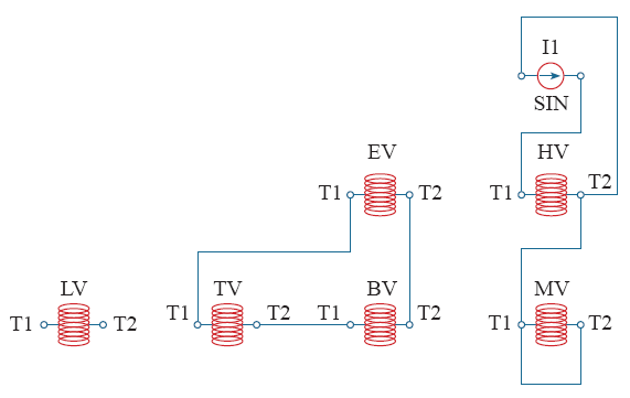
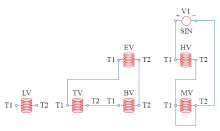
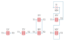
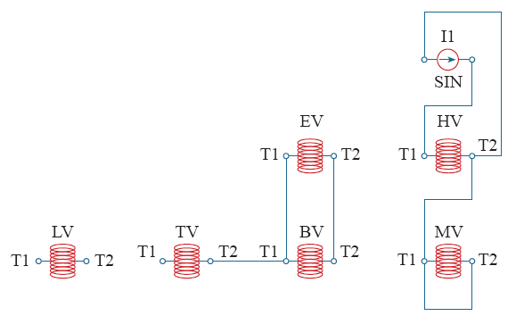
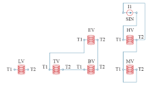
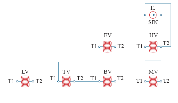
Fig.5
HVmax-MV no load operation equivalent circuit"
Tab.1
Comparison between calculation results of winding no-load phase voltage of HVmax-MV"
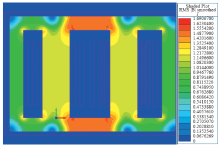
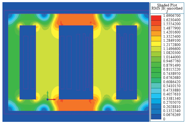
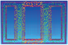
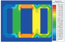
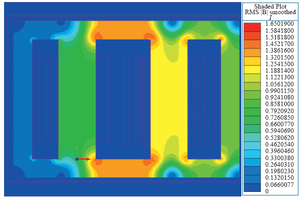
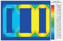
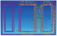
Fig.6
Magnetic flux distribution in iron core with no-load operation HVmax-MV"
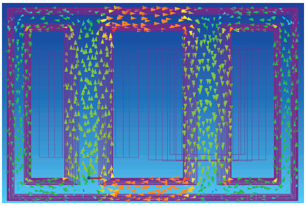
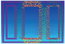
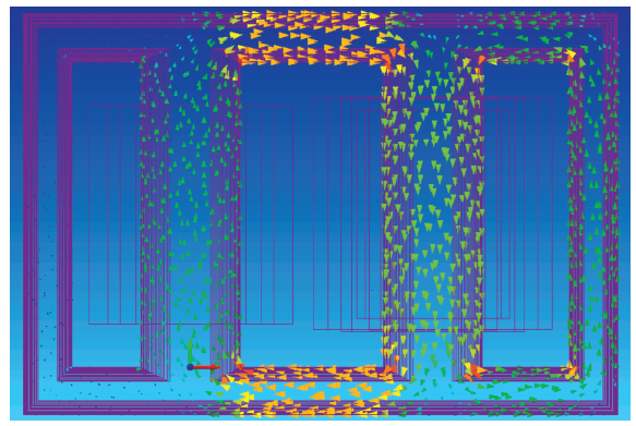
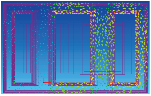
Fig.7
Magnetic density vector diagram of HVmax-MV no-load operation core"
Tab.2
Comparison between calculation results of magnetic flux density of main column for no-load operation HVmax-MV"
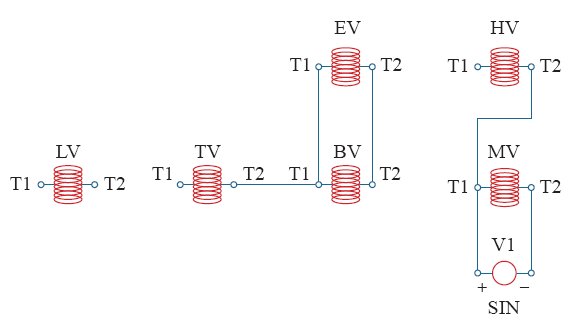
Fig.8
HVmax-MV short-circuit operation equivalent circuit"
Tab.3
Comparison of calculation results of phase currents in HVmax-MV short-circuit winding"
Fig.9
Tab.4
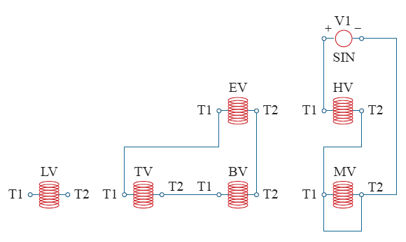
Fig.10
HVrat-MV no-load operation equivalent circuit"
Tab.5
Comparison between calculation results of phase-ground voltage of no-load HVrat-MV"
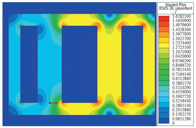
Fig.11
Magnetic flux distribution in iron core of no-load operation HVrat-MV"
Fig.12
Magnetic density vector diagram of HVrat-MV no-load operation core"
Tab.6
Comparison between calculation results of magnetic flux density in main column for no-load operation HVrat-MV"
Fig.13
HVrat-MV short-circuit operation equivalent circuit"
Tab.7
Comparison of calculation results of phase currents in HVrat-MV short-circuit winding"
Fig.14
Tab.8
Comparison between calculation results of phase currents in HVrat-MV short-circuit winding"
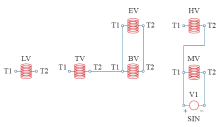
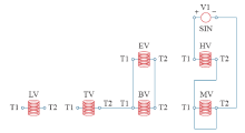
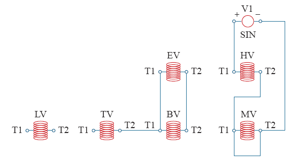
Fig.15
HVmin-MV no-load operation equivalent circuit"
Tab.9
Comparison between calculation results of phase voltage of no-load HVmin-MV"
Fig.16
Magnetic flux distribution in iron core of no-load HVmin-MV"
Fig.17
Magnetic density vector diagram of HVmin-MV no-load operation core"
Tab.10
Comparison between calculation results of magnetic flux density in main column of no-load HVmin-MV"
Fig.18
HVmin-MV short-circuit operation equivalent circuit"
Tab.11
Comparison between short-circuit currents calculating results of HVmin-MV winding"
Fig.19
Tab.12
Tab.13
Comparison between single core and double cores"